39 Results
View results:
Sort by:

The data exchange between RFEM 6 and Allplan can be done using various file formats. This article describes the data exchange of a determined surface reinforcement using the ASF interface. This allows you to display the RFEM reinforcement values as level curves or colored reinforcement images in Allplan.

The fatigue design according to EN 1992-1-1 must be performed for the structural components subjected to large stress ranges and/or many load changes. In this case, the design checks for the concrete and the reinforcement are performed separately. There are two alternative design methods available.
If you want to only change a few geometry parameters in a model, it is not always necessary to remove these structural parts and redefine them.

In the age of BIM, data exchange between the various disciplines of structural engineering is becoming increasingly important. Since each software has its own specifications with regard to the description of cross-sections and materials, RFEM and RSTAB offer a conversion table (mapping file).

RFEM and RSTAB offer many display options in the Display Navigator. They can be completely different, depending on their function. You often have to click several times to make certain changes. If you want to optimize your work, you can create user‑defined views. In these views, you can save all specified settings. The following example illustrates this principle.

If the geometry of a surface for which you must remove some of the existing boundary lines changes subsequently, you do not need to redefine the surface.

The same structures are often needed in several projects, such as the purlin with columns and braces in this example. The dimensions can be changed directly in RFEM or RSTAB by shifting the nodes.
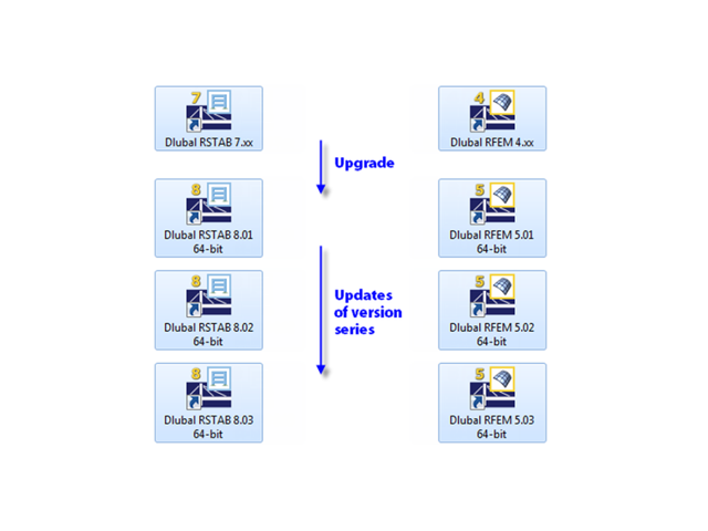
When updating within a version series (for example, RFEM 5.01.01 to 5.01.02), the old program files are removed and replaced by new ones. The project data, of course, remain unchanged. When updating to the next version series (for example, RFEM 5.02.01), the new version is installed in parallel. The program files are located in different directories, so the previous version is still available.
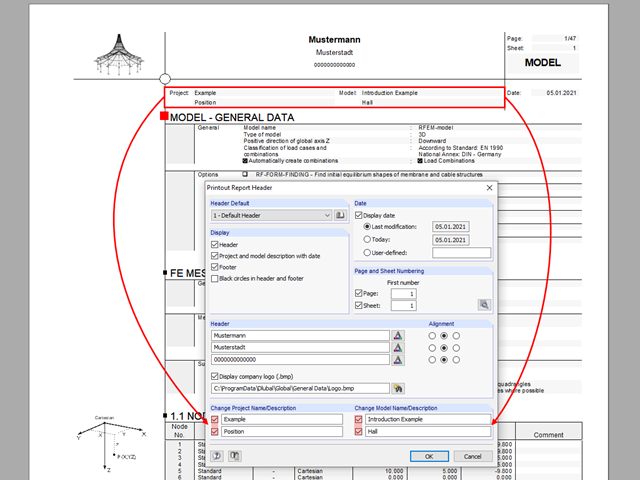
The name of the project/model from the General Data is shown in the header of the printout report by default. In RFEM 5 and RSTAB 8, the model name can be changed manually in the printout report independently of the actual name.

According to Book 631 of the DAfStb (German Committee for Structural Concrete), Chapter 2.4, the structural behavior of ceilings changes if their continuous support by walls is interrupted in areas of openings. Depending on the length of the opening area and the plate thickness, measures are necessary regarding the analysis of the ceiling in the area of the opening.
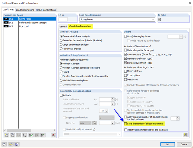
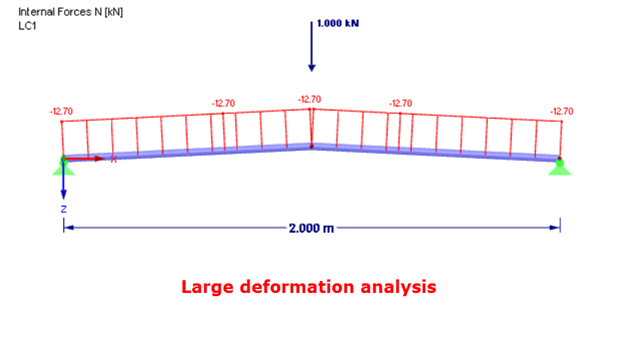
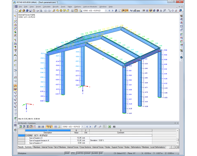
The calculation in RFEM is usually carried out in several calculation steps (iterations). It is then possible to consider particular characteristics of the model, such as objects with nonlinear functions. In addition, by using the iterative calculation, nonlinear effects are taken into account that result from changes in deformation and internal forces in case of the second-order analysis or when considering large deformations (cable theory). In case of complex models, geometric linear calculations are usually insufficient.
Daniel Dlubal's bachelor's thesis focuses on presenting and highlighting the chances, advantages, and opportunities of BIM when performing the structural analysis and design of buildings. The essential information of a structural analysis is shown and the data exchange between the CAD and the structural engineering software is explained in detail as well.
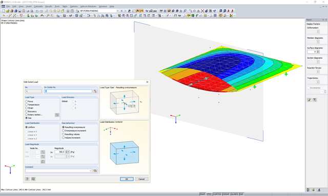
In theory, an ideal gas consists of freely moving mass particles without extension in a volume space. In this space, each particle moves at a speed in one direction. The collision of one particle with another particle or the volume limitations leads to a deflection and a change in the speed of the particles.
In the BIM workflow, IFC files are frequently used as the basis for data exchange between CAD and structural engineering software. However, there is a fundamental problem with this approach. This article explains various types of IFC files and provides an overview of the import and export options in Dlubal Software programs.
In the case of a post-critical failure, a substantial change occurs in the geometry of a structure. After reaching the instability of the equilibrium, a stable, strength position is reached again. The post-critical analysis requires an experimental approach. It is necessary to manually load the structure in increments step by step.
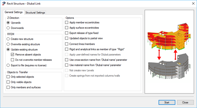
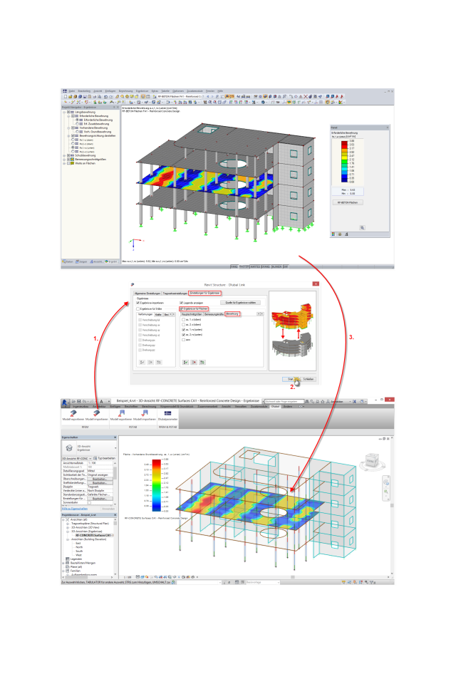
BIM is often used when it comes to data management in civil engineering. The individual disciplines of architecture, structural design, construction, and structural monitoring are coming closer together. Building Information Modeling makes this possible.. Dlubal Software provides a wide range of formats for data exchange. The following article explains the details of the interface with Autodesk Revit and, in particular, the export settings.
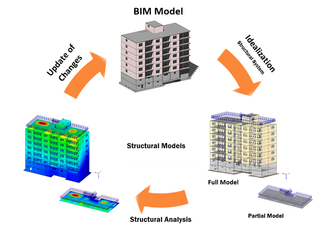
Building Information Modeling describes what is possibly one of the most important current topics in the entire construction software industry. However, the process is not that new, and it is a well-known fact that the total costs of a project can be positively influenced by good planning in the initial stage.
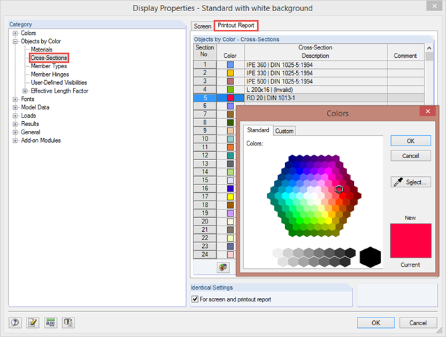
By clicking "Options" → "Display Properties" → "Edit", you can change and save display settings for printout reports and your screen. For example, you can set individual colors for cross‑sections.
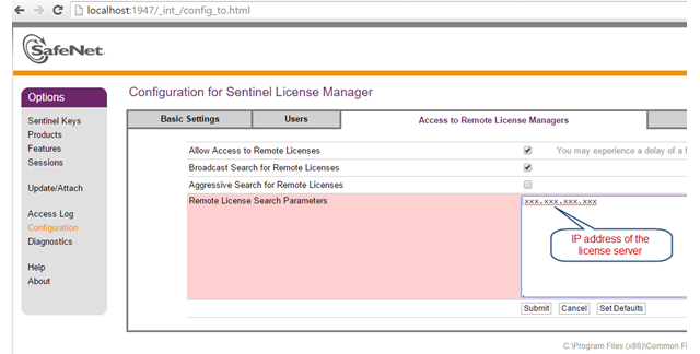
The network licenses of Dlubal Software provide a very convenient solution for engineering offices as well as for users who are often on the move. This can be helpful if you are in a consulting meeting with a building owner and want to directly apply the current changes and show the solution immediately. You only need an Internet and a VPN connection in your office to access all your purchased licenses.
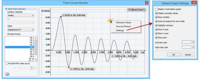
The Time Course Monitor displays the results of a time history analysis from RF‑/DYNAM Pro – Forced Vibrations. The graphic can be adjusted in the settings. This can be reached by right-clicking in the shortcut menu. For example, you can activate or deactivate the grid in the graphic. Those changes are overtaken into the printout report when you print the graphic.

As in RFEM, load combinations can be generated automatically in RF‑PIPING. This feature is activated by default and creates the recommended load and result combinations for piping design. It is necessary to assign the relevant action category to load cases in order to generate the correct combinations. To do this, new action categories have been implemented specifically for loads on piping.
Pressure temperature conditions are generated as the sets of the first (second, third, and so on) load case of the "Pressure" category and the first (second, third, and so on) load case of the "Temperature" category. The default setting can be reviewed or adjusted in the "Grouping of Thermal and Internal Pressure Load Cases for Operating Combinations" dialog box. You can access this dialog box by clicking the corresponding button in the "Piping Load Combinations" tab of the "Load Cases and Combinations" dialog box. This dialog box is automatically offered to check your entries in the case of any change of the load case from the "Pressure" or "Temperature" category.
Pressure temperature conditions are generated as the sets of the first (second, third, and so on) load case of the "Pressure" category and the first (second, third, and so on) load case of the "Temperature" category. The default setting can be reviewed or adjusted in the "Grouping of Thermal and Internal Pressure Load Cases for Operating Combinations" dialog box. You can access this dialog box by clicking the corresponding button in the "Piping Load Combinations" tab of the "Load Cases and Combinations" dialog box. This dialog box is automatically offered to check your entries in the case of any change of the load case from the "Pressure" or "Temperature" category.
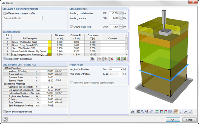
As of program version x.06.1103, you can enter a soil profile in RF‑/FOUNDATION Pro. This gives you the advantage of setting several soil layers with different soil parameters above and below the foundation base. To enter the soil layers, there is a library with various soil types that can also be extended with user‑defined soils. The user-defined soil profile is shown in an interactive information graphic. Any change (for example, a soil thickness modification) is reflected in the graphic immediately.
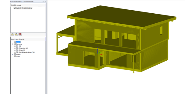
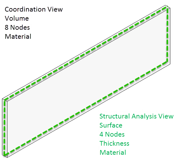
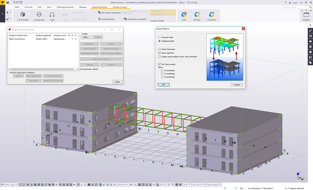
The "Coordination View 2.0" Import allows you to import virtually any physical models from various programs into RFEM/RSTAB to generate an analytical model.
The Master's Thesis of Tamás Drávai, Haroon Khalyar, and Gábor Nagy deals with the effect of interoperability between Computer Aided Design (CAD) and Finite Element Modeling (FEM) software on structural modeling and analysis. Several case studies were conducted, where a building information model was transferred from CAD to FEM software with different data exchange formats.
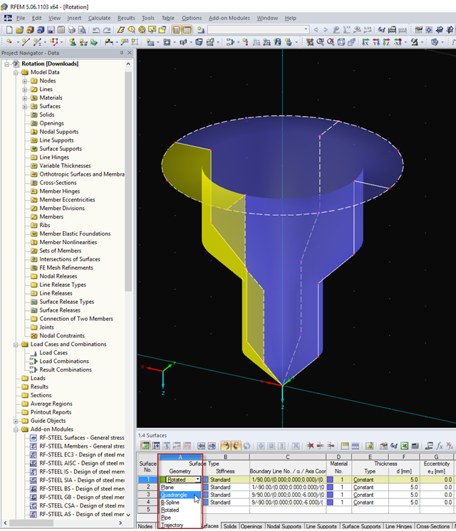
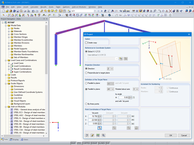
You can quickly model very complex objects in RFEM by rotating lines or polylines. If you need to change the model subsequently, quadrangle surfaces provide an advantage, as they include editable boundary lines.
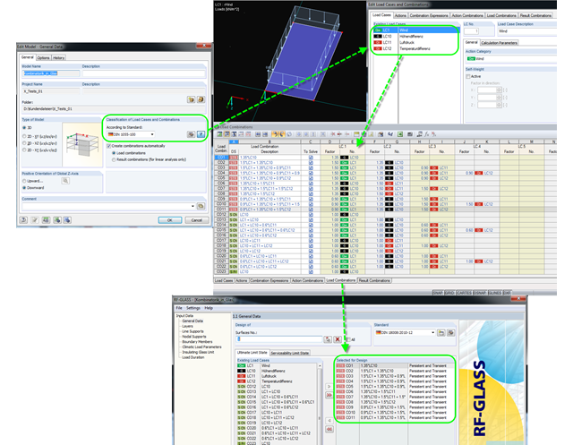
For the superposition or combination of loads, the German standard DIN 18008 refers to DIN 1055‑100. This also applies for the individual parameters of climatic loads to be transferred. In this case, it is possible to summarize the temperature change and meteorological pressure change in a single load and to define the local altitude change as a permanent load.
You can change the content and appearance of a toolbar under "View" → "Arrange Toolbars Customized". This way, you can easily arrange and save frequently used commands in specific user‑defined toolbars. In addition to the default arrangement on the top of the screen, you can dock the toolbars on the left and right edges of the screen for a better overview.
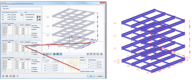
Arranging a model into an axis can provide better visibility, and in addition, the line grid can allow you to apply changes quickly in the model.

In RF-STEEL Surfaces, it is possible to display the stresses relevant for the design of welds, for example, according to EN 1993‑1‑8, Figure 4.5. When evaluating the stress components, the local xyz-axis system of the surfaces must be considered.
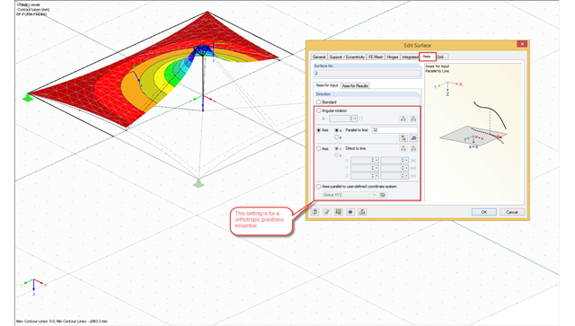
The form-finding process in RFEM seeks an equilibrium state where the defined prestress of membranes and the prestress or length changes of cable elements with boundary reactions are in equilibrium. For this, the program provides the option to define an isotropic or an orthotropic prestress state for membranes.